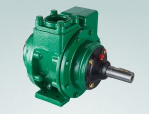
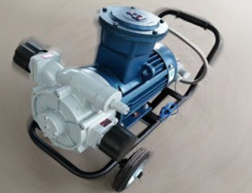
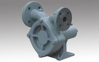
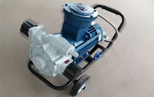
Self-priming Pump CBH-80
Self-priming pump CBH-80 and its units (hereinafter referred to as pumps or units) are designed to pump liquids without 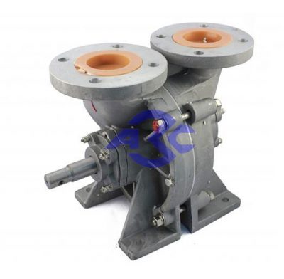 mechanical impurities. Pump CBH-80 is designed to pump the following liquids: water, gasoline, kerosene, diesel fuel and other liquids with a viscosity of not more than 2×10⁻⁶m2/s at a temperature from -40̊С to +50̊С and a density of not more than 1000 kg/m3.
Symbol of a pump or electric pump unit:
C – self-priming(самовсасывающий);
B – vortex (вихревой);
H-pump (насос);
80- DN inlet and outlet pipe, mm
Specifications of Pump CBH-80
The main technical characteristics of the pump are shown in Fig . 1 and in Table 1 at testing it on water at a temperature of 20 °C and a rotational speed of 1450 rpm.
The choice of the recommended operating interval for the performance of pumps is carried out according to Fig.1.
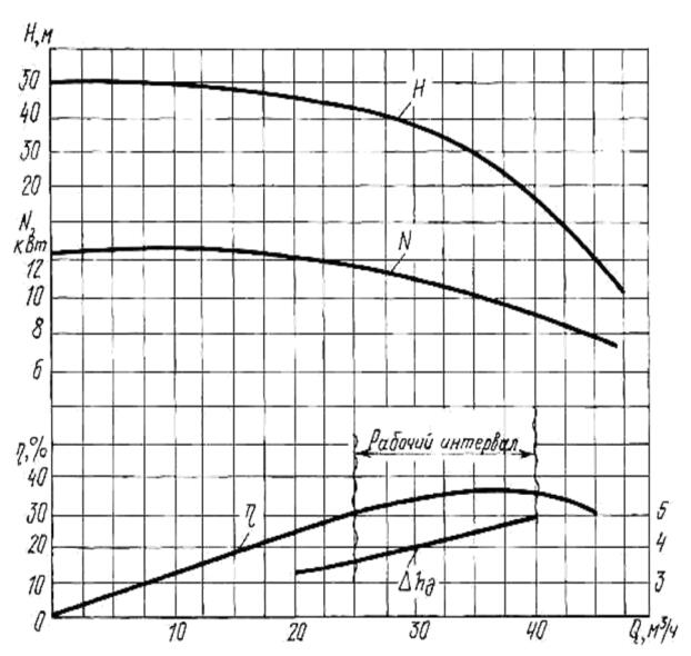
Table 1 – Specifications of Pump CBH-80
| Model | CBH-80 |
| Rated pump power, W | 7500 |
| Voltage, V | 380 |
| Rotation frequency, s-1 (rpm) | 1450 |
| Direction of pump rotation | Right or Left |
| Supply,m3/h | 30 |
| Rated head, m | 26 |
| Self-priming height, not less than, m | 6.5 |
| Self-priming time, no more than, s | 120 |
| Permissible duration of self-priming, no more than, s | 300 |
| Leakage through the mechanical seal, not more than cm3/h | 30 |
| Electric motor power, kW | 11 or 15 |
| Pump weight | 19kg |
Figure2. Overall and connecting dimensions of pumps of the right rotation.
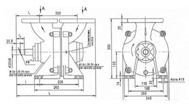
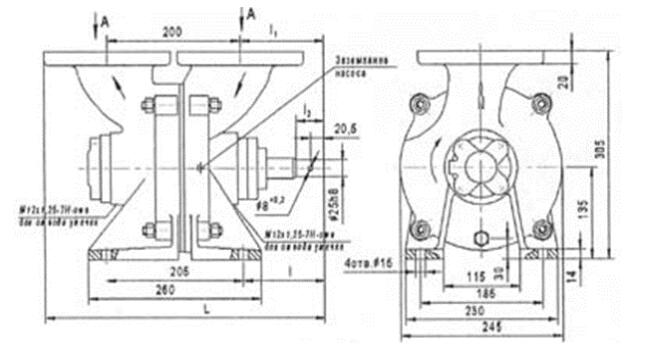
Figure3. Overall and connecting dimensions of pumps of the left rotation.
Device & operation
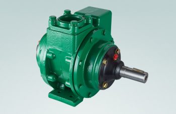
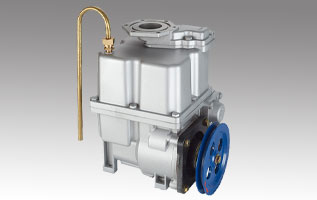
- The pumps are available in right (Fig. 2) and left (Fig. 3) rotation. The direction of rotation is determined by the position of the pump output shaft.
- Before switching on, the pump is filled with working fluid. At the time of starting, the liquid available in the pump, is captured by the blades of the Wheel 2 and is thrown along the working channel into Pressure section 3. At the same time, part of the liquid enters the blind channel and is forced out into the interscapular space of the Wheel 2, thanks to the jumper in the working channel. An increase in the volume of fluid in the periphery of the interscapular space leads to the displacement of air at the wheel hub into the outlet. This process continues until all air has been evacuated from the suction pipe, and the pumped liquid will not fill the vacated volume. Kinetic energy rotating Wheel 2 is transferred to the pumped liquid and it enters pressure pipeline. The vacated space is refilled pumped liquid. This process occurs continuously during pump operation.
- Gradually closing the pressure valve, set the operating mode of the pump.
ATTENTION!
- It is not allowed to start the pump without liquid filling;
- Do not operate the pump in self-priming mode for more than five minutes. It may lead to heating of the working parts of the pump and their jamming.
Safety instructions
- The pump CBH-80 must comply with the requirements of GOST 12.2.003-91.
- Only a qualified person is allowed to install and operate the pump or unit.Personnel who have access to work and have studied the design of the pump and its parameters.
- The pump casing and the unit must be properly grounded. The ground bolt is on the body in the area of the suction section.
- Leakage of the pumped liquid through the flange connectionsand pipelines in the pump is not allowed.
- When the pump is running, it is forbidden to tighten the bolts of the flange connections andlubricate the bearings.
- It is not allowed to start the pump if the pumped liquid is not filled into the casing.
- In explosive and fire hazardous industries, it is necessary to useautomatic protection. The terms of reference determine the choice of protection scheme.
- Pipelines must have their own supports, excluding the transfer of forces to pump.
Prepare for work
- Before installation, check the scope of delivery of the pump or unit, the integrity of the seals, the presence of plugs on the suction and pressure pipes, turning the wheel shaft pump with force up to 5 N×m.
- The pump or unit is only supplied assembled and does not require disassembly for installation. Depreservation procedure: pour 2-3 liters into the pump through a funnel with a mesh gasoline and turn the pump shaft several times by hand.
- Pumps or units for pumping light petroleum products conservation do not produce. Before installation, flush the pump cavity with a 5% solution of baking soda at a temperature of + 50-60̊С for two to three minutes.
- Pumps for pumping water and food liquids must be depreserved before installation. Rinse for thirty minutes: with one of the solutions (caustic soda 0.8-2% at t = 70-80̊C or nitric or sulfamic acids 0.3-1.5% at t=65-70̊C).
- Install a mesh filter on the suction pipe 1…1.5 mm.
- Connect the suction and pressure pipes. vertical section pressure pipeline must be at least 260 mm. Suction pipeline should be airtight and as short as possible.
Maintenance
- It is necessary to check the instrument readings at least once a week, the degreeheating of bearings, the condition and quality of the lubricant, the amount of leakage of the working fluid through seals, tightness of fasteners.
- Bearings must be lubricated every 1000 operating hours or once everythree months with grease Litol-24 GOST 21150-87 using a press syringe through oilers, screwed into the bearing caps.
- It is necessary to keep a Logbook of the operation of the pump or unit (Appendix B) fordetermination of working time. Enter in the journal the work carried out on maintenance and malfunctions that have occurred.
- During operation, the pump and motor must be grounded. Groundingelectric motor in accordance with GOST 12 2.00.0-75, grounding of the pump in accordance with GOST 21130-75.
Leave A Comment